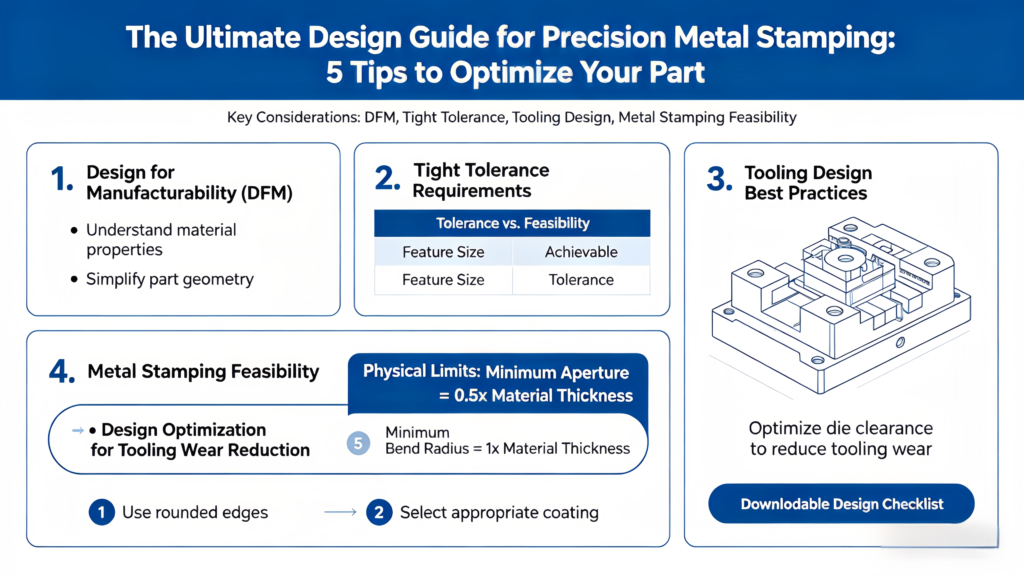
Google Featured Snippet: Precision metal stamping is a critical manufacturing process for producing high-quality Metal Stamping Parts with tight tolerances, but its efficiency and cost-effectiveness depend heavily on design for manufacturability (DFM), tooling design, and metal stamping feasibility. This guide breaks down 5 actionable tips to optimize your Custom Metal Stamping parts—covering physical constraints like minimum hole size and bend radius, tooling wear reduction, and practical design strategies. Plus, you’ll get access to a downloadable Design Checklist to ensure every step of your Precision Stamping process aligns with industry best practices, whether you’re working with Sheet Metal Stamping, Stainless Steel Stamping, or partnering with a Stamping Manufacturer.
Introduction: Why Precision Metal Stamping Design Matters for Engineers
For engineers tasked with designing Metal Stamping Parts—whether for automotive, aerospace, medical, or industrial applications—precision is non-negotiable. Precision Stamping demands a delicate balance between design ambition and manufacturing reality, where even the smallest oversight can lead to costly delays, poor part performance, or premature tool failure. Custom Metal Stamping, in particular, requires meticulous attention to detail, as each unique part must meet specific functional requirements while remaining cost-effective to produce.
The goal of this guide is to empower engineers with actionable insights to optimize their stamping designs, focusing on four core pillars: Design for Manufacturability (DFM), tight tolerance management, tooling design optimization, and metal stamping feasibility. By mastering these elements, you’ll not only reduce production costs and lead times but also ensure your Sheet Metal Stamping, Stainless Steel Stamping, or other stamping projects deliver consistent, high-quality results—whether you’re working with an in-house team or a trusted Stamping Manufacturer.
We’ll dive deep into the physical constraints that govern precision metal stamping, explain how to design parts that minimize模具损耗 (tooling wear), and provide a clear, step-by-step framework to validate your design’s feasibility. Most importantly, we’ve included a downloadable Design Checklist to streamline your workflow and ensure no critical detail is overlooked—giving you confidence that your design is ready for production.
Whether you’re a seasoned engineer with years of experience in Metal Stamping Parts or a newcomer to Custom Metal Stamping, this guide will serve as a comprehensive resource to elevate your design process. Let’s start by exploring the foundational concepts that underpin successful precision stamping design.
Tip 1: Understand the Physical Constraints of Precision Metal Stamping
Precision Stamping relies on the controlled deformation of metal sheets to create complex shapes, but every material and stamping process has inherent physical limits. Ignoring these constraints can lead to part defects, tool damage, or even production failure. As an engineer, your first step in optimizing a stamping design is to familiarize yourself with the key physical constraints, including minimum hole size, bend radius, material thickness, and grain direction—all of which directly impact Metal Stamping Parts quality and manufacturability.
1.1 Minimum Hole Size: Balancing Function and Feasibility
One of the most common design pitfalls in Custom Metal Stamping is specifying a hole size that is too small for the material and stamping process. The minimum hole size in Sheet Metal Stamping or Stainless Steel Stamping is determined by three key factors: material type, material thickness, and the stamping method (e.g., blanking, piercing). Failing to adhere to these limits can result in broken punches, uneven hole edges, or parts that do not meet tight tolerance requirements.
For most metals used in precision stamping (e.g., steel, aluminum, stainless steel), the minimum hole diameter should be at least 1.2 times the material thickness. However, this ratio can vary based on material hardness—harder materials like Stainless Steel Stamping require a larger minimum hole size, while softer materials like aluminum can accommodate slightly smaller holes. Below is a detailed table outlining the minimum hole size for common materials used in Metal Stamping Parts, along with key considerations for DFM and tight tolerance management.
| Material Type | Material Thickness (t) | Minimum Hole Diameter (Recommended) | Tight Tolerance Range for Holes | DFM Considerations |
|---|---|---|---|---|
| Mild Steel (1010/1018) | 0.5mm – 3.0mm | 1.2t – 1.5t | ±0.02mm – ±0.05mm | Avoid holes closer than 2t to part edges; use rounded punch tips to reduce tool wear |
| Stainless Steel (304/316) | 0.5mm – 3.0mm | 1.5t – 2.0t | ±0.03mm – ±0.06mm | Harder material requires larger hole size; use coated punches to improve wear resistance |
| Aluminum (6061/5052) | 0.5mm – 3.0mm | 1.0t – 1.2t | ±0.02mm – ±0.04mm | Softer material allows smaller holes; avoid burrs by using proper punch-die clearance |
| Copper/Brass | 0.5mm – 3.0mm | 1.1t – 1.3t | ±0.02mm – ±0.05mm | Ductile material; ensure punch alignment to prevent hole distortion |
When designing holes for Precision Metal Stamping, it’s also critical to consider the distance between holes and the part edge. A general rule of thumb is that the distance from the edge of a hole to the nearest part edge should be at least 2 times the material thickness. This prevents the material from tearing or warping during stamping, which can compromise tight tolerances and part integrity. For example, if you’re designing a Stainless Steel Stamping part with a thickness of 2mm, the hole should be at least 4mm away from the part edge.
Another key DFM consideration for holes is punch-die clearance. The clearance between the punch and die directly affects hole quality and tool life. For most Metal Stamping Parts, the optimal clearance is 5-10% of the material thickness for soft metals and 10-15% for hard metals like stainless steel. Incorrect clearance can lead to burrs (too little clearance) or uneven hole edges (too much clearance), both of which require additional finishing steps and increase production costs. A trusted Stamping Manufacturer can help you determine the optimal clearance for your specific material and design.
1.2 Bend Radius: Avoiding Material Fatigue and Cracking
Bending is a common operation in Sheet Metal Stamping and Custom Metal Stamping, but specifying an overly tight bend radius can lead to material cracking, especially in harder metals like stainless steel. The minimum bend radius is the smallest radius you can bend a metal sheet without causing permanent damage, and it is determined by the material’s ductility, thickness, and grain direction.
For ductile materials (e.g., aluminum, copper), the minimum bend radius can be as small as 0.5 times the material thickness. For harder materials (e.g., stainless steel, high-strength steel), the minimum bend radius is typically 1.0-2.0 times the material thickness. Below is a summary of minimum bend radii for common stamping materials, along with tips to optimize bend design for tight tolerance and tooling longevity.
| Material Type | Material Thickness (t) | Minimum Bend Radius (Inside) | Grain Direction Consideration | Tooling Design Tips |
|---|---|---|---|---|
| Mild Steel (1010/1018) | 0.5mm – 3.0mm | 0.5t – 1.0t | Bend across grain direction for better ductility | Use radius dies to prevent sharp edges; avoid re-bending the same area |
| Stainless Steel (304/316) | 0.5mm – 3.0mm | 1.0t – 2.0t | Grain direction has minimal impact; focus on material hardness | Use hardened dies to resist wear; apply lubrication to reduce friction |
| Aluminum (6061/5052) | 0.5mm – 3.0mm | 0.3t – 0.5t | Bend along grain direction to avoid cracking | Use soft dies to prevent marring; maintain consistent bend angle |
| Copper/Brass | 0.5mm – 3.0mm | 0.4t – 0.8t | Grain direction is negligible for most applications | Use polished dies to ensure smooth bend surfaces |
When designing bends for Precision Metal Stamping, it’s also important to consider the bend angle and the distance between bends. Sharp bend angles (less than 90 degrees) can increase material stress and tool wear, while bends that are too close together can cause material distortion. A general guideline is to keep the distance between bends at least 3 times the material thickness. Additionally, avoiding re-bending the same area of the part will prevent material fatigue and cracking, ensuring the part meets tight tolerance requirements over time.
For Custom Metal Stamping projects that require complex bends, working with a Stamping Manufacturer early in the design process is critical. They can provide insights into the feasibility of your bend design, recommend adjustments to improve manufacturability, and help you select the right tooling to minimize wear and ensure consistent results. This collaboration is a key part of DFM and metal stamping feasibility assessment.
1.3 Material Thickness and Grain Direction: Foundation of Stamping Success
The thickness of the metal sheet used in Sheet Metal Stamping or Stainless Steel Stamping directly impacts every aspect of the stamping process—from tooling design to tight tolerance management. Thicker materials require more force to stamp, which increases tool wear and can limit the complexity of the part design. Thinner materials, while easier to stamp, are more prone to warping and require careful handling to maintain precision.
When selecting material thickness for Metal Stamping Parts, it’s important to balance functional requirements with manufacturability. For example, a part that requires high strength may need a thicker material, but this will increase production costs and tooling wear. By optimizing the design to use the thinnest material possible while meeting strength requirements, you can reduce costs and improve stamping efficiency—a core principle of DFM.
Grain direction is another critical factor in Precision Stamping, especially for materials with a distinct grain structure (e.g., steel, aluminum). The grain direction is the direction of the metal’s crystalline structure, which forms during the rolling process. Bending or stamping across the grain direction (perpendicular to the grain) can lead to material cracking, while bending along the grain direction (parallel to the grain) improves ductility and reduces the risk of damage.
For example, in Sheet Metal Stamping of mild steel, bending across the grain direction can reduce the minimum bend radius by up to 50%, increasing the risk of cracking. By aligning bends along the grain direction, you can achieve tighter bend radii while maintaining part integrity. This is especially important for Custom Metal Stamping parts that require tight tolerances and high reliability, such as automotive or medical components.
When working with a Stamping Manufacturer, be sure to specify the grain direction requirements for your Metal Stamping Parts. They can help you source materials with the correct grain orientation and adjust the stamping process to align with your design needs. This attention to detail will ensure your parts meet tight tolerance requirements and perform reliably in their intended application.
Tip 2: Optimize Design for Manufacturability (DFM) to Reduce Costs and Improve Quality
Design for Manufacturability (DFM) is the cornerstone of successful Precision Metal Stamping. DFM is the practice of designing parts with the manufacturing process in mind—ensuring that the design is feasible, cost-effective, and capable of producing consistent, high-quality Metal Stamping Parts. By integrating DFM principles into your design process, you can reduce production costs, shorten lead times, minimize defects, and extend tool life—all while meeting tight tolerance requirements.
For engineers, DFM requires a shift from “designing what you want” to “designing what can be manufactured efficiently.” This means considering every aspect of the stamping process—from material selection to tooling design to post-stamping finishing—early in the design phase. Below are key DFM strategies to optimize your Custom Metal Stamping, Sheet Metal Stamping, or Stainless Steel Stamping designs.
2.1 Simplify Part Geometry to Minimize Tooling Complexity
Complex part geometries—such as sharp corners, intricate cutouts, or uneven surfaces—require complex tooling, which increases costs and tool wear. By simplifying the part geometry, you can reduce tooling complexity, improve stamping efficiency, and lower production costs. This is especially important for Precision Stamping, where tight tolerances demand consistent tool performance.
For example, replacing sharp corners with rounded edges (fillets) can reduce tool stress and prevent cracking in the part. Fillets also improve the flow of material during stamping, ensuring consistent deformation and reducing the risk of defects. The recommended fillet radius for Metal Stamping Parts is at least 0.5 times the material thickness, though larger radii are preferred for harder materials like stainless steel.
Another way to simplify geometry is to minimize the number of features (e.g., holes, notches, bends) in the part. Each additional feature requires additional tooling (e.g., punches, dies) and increases the risk of misalignment, which can compromise tight tolerances. By combining features or eliminating non-essential ones, you can reduce tooling costs and improve stamping consistency.
For Custom Metal Stamping projects, working with a Stamping Manufacturer early in the design phase can help you identify opportunities to simplify part geometry. They can provide feedback on which features are feasible, which can be simplified, and how to adjust the design to reduce tooling complexity. This collaboration is critical for ensuring metal stamping feasibility and optimizing the design for cost and quality.
2.2 Standardize Features to Reduce Tooling Costs
Standardizing features across your Metal Stamping Parts is a key DFM strategy to reduce tooling costs and improve efficiency. If you’re designing multiple parts for a project, using the same hole sizes, bend radii, and material thicknesses can allow you to reuse tooling, reducing the need for custom tooling and lowering production costs. This is especially beneficial for high-volume Precision Stamping projects.
For example, if you’re designing a series of Sheet Metal Stamping parts for an automotive assembly, standardizing the hole size to 5mm (where possible) allows you to use the same punch for all parts, reducing tooling costs and simplifying the stamping process. Similarly, standardizing bend radii and material thicknesses ensures consistent tool wear and makes it easier to maintain tight tolerances across all parts.
Standardization also extends to material selection. Using the same material (e.g., 304 stainless steel) for multiple parts can reduce sourcing costs and simplify the stamping process, as the Stamping Manufacturer can optimize the process for a single material. This consistency also improves quality control, as the material properties (e.g., ductility, hardness) will be the same across all parts.
When standardizing features, it’s important to balance standardization with functional requirements. While standardizing hole sizes can reduce costs, you must ensure the hole size meets the part’s functional needs (e.g., for fasteners or fluid flow). A trusted Stamping Manufacturer can help you identify the optimal balance between standardization and functionality, ensuring your parts meet both performance and cost goals.
2.3 Design for Easy Material Flow and Reduced Scrap
Material flow during stamping is critical to producing high-quality Metal Stamping Parts with tight tolerances. Poor material flow can lead to defects like wrinkles, tears, or uneven deformation, which require additional finishing steps or result in scrap. By designing parts to promote smooth material flow, you can reduce scrap rates, improve part quality, and extend tool life.
One key strategy to improve material flow is to use gradual transitions between features. For example, instead of sharp transitions between a flat surface and a bend, use a fillet to create a smooth transition. This allows the material to deform evenly during stamping, reducing stress and preventing defects. Similarly, avoiding sudden changes in part width or thickness can improve material flow and reduce the risk of wrinkling.
Another important DFM consideration is nesting—arranging multiple parts on a single metal sheet to minimize scrap. For Sheet Metal Stamping or Stainless Steel Stamping, efficient nesting can reduce material waste by up to 30%, lowering production costs. When designing parts, consider their shape and size to optimize nesting. For example, parts with irregular shapes can often be nested more efficiently if their design is adjusted to fit together like puzzle pieces.
A Stamping Manufacturer can help you optimize nesting for your Custom Metal Stamping parts, using specialized software to arrange parts in the most efficient way possible. They can also provide feedback on part design adjustments that can improve nesting efficiency, such as adjusting the part’s shape or size to reduce gaps between nested parts.
Tip 3: Master Tight Tolerance Management for Precision Metal Stamping
Tight tolerance is one of the defining characteristics of Precision Stamping, and it’s critical for parts that require precise fit and function—such as automotive components, medical devices, and aerospace parts. Tight tolerance refers to the allowable variation in a part’s dimensions (e.g., hole size, bend angle, overall length), and managing these tolerances effectively is essential to ensuring part quality and performance.
For engineers, tight tolerance management requires a deep understanding of the stamping process, material properties, and tooling performance. Below are key strategies to master tight tolerance management for your Metal Stamping Parts, whether you’re working with Custom Metal Stamping, Sheet Metal Stamping, or Stainless Steel Stamping.
3.1 Define Realistic Tolerances Based on Function and Feasibility
One of the most common mistakes in Precision Stamping design is specifying tolerances that are tighter than necessary. While tight tolerances may seem like a way to ensure part quality, overly tight tolerances increase production costs, extend lead times, and increase the risk of defects. The key is to define tolerances based on the part’s functional requirements—not just industry standards.
For example, a hole that is used to mount a fastener may require a tight tolerance of ±0.02mm to ensure a secure fit, while a non-critical feature (e.g., a decorative notch) may only require a tolerance of ±0.1mm. By prioritizing tolerances based on function, you can reduce costs and improve manufacturability while still meeting the part’s performance needs.
When defining tolerances, it’s also important to consider metal stamping feasibility. Some tolerances may be too tight for the stamping process or material to achieve consistently. For example, a tolerance of ±0.01mm for a hole in a 2mm thick stainless steel sheet may be feasible with advanced Precision Stamping equipment, but it will require specialized tooling and stricter quality control, increasing costs. A Stamping Manufacturer can help you determine the most realistic tolerances for your design, based on the material, stamping process, and tooling capabilities.
3.2 Optimize Tooling Design to Maintain Tight Tolerances
Tooling design is directly linked to tight tolerance management in Precision Stamping. Poorly designed tooling can lead to inconsistent part dimensions, tool wear, and defects—all of which compromise tolerances. By optimizing tooling design, you can ensure consistent part dimensions, extend tool life, and maintain tight tolerances over high-volume production runs.
Key tooling design considerations for tight tolerance include: Punch and Die Alignment: Proper alignment between the punch and die is critical to ensuring consistent hole sizes and part dimensions. Misalignment can lead to uneven hole edges, distorted parts, and increased tool wear. Using precision-guided tooling (e.g., guide pins, bushings) can improve alignment and maintain tight tolerances.Tool Material Selection: The material used for punches and dies directly impacts tool life and tolerance consistency. For high-volume Precision Stamping or Stainless Steel Stamping, using hardened tool steel (e.g., D2, A2) or carbide can improve wear resistance and maintain tight tolerances over time. Coated tooling (e.g., TiN, TiCN) can further extend tool life by reducing friction and wear.Tool Maintenance: Regular tool maintenance is essential to maintaining tight tolerances. Over time, punches and dies wear down, leading to larger hole sizes, uneven bends, and other dimensional errors. Establishing a regular maintenance schedule (e.g., sharpening punches, replacing worn dies) can ensure tooling remains in optimal condition and tolerances are maintained.
For Custom Metal Stamping projects that require extremely tight tolerances, working with a Stamping Manufacturer that specializes in precision tooling is critical. They can design and manufacture tooling that is tailored to your specific tolerance requirements, using advanced machining techniques to ensure tooling precision.
3.3 Implement Quality Control Measures to Monitor Tolerances
Even with optimized design and tooling, maintaining tight tolerances requires robust quality control (QC) measures. QC ensures that every Metal Stamping Part meets the specified tolerances, reducing the risk of defective parts reaching the end user. Below are key QC measures to implement for Precision Stamping:
In-Process Inspection: Inspecting parts during the stamping process (e.g., every 100 parts) allows you to identify tolerance issues early, before they lead to large quantities of scrap. In-process inspection can include measuring key dimensions with calipers, micrometers, or coordinate measuring machines (CMMs).Statistical Process Control (SPC): SPC is a data-driven approach to monitoring and controlling the stamping process. By collecting and analyzing data on part dimensions, you can identify trends and variations, and make adjustments to the process to maintain tight tolerances. SPC is especially useful for high-volume Precision Stamping projects, where consistent tolerances are critical.Final Inspection: A final inspection of every part (or a random sample, depending on volume) ensures that only parts meeting the specified tolerances are shipped. Final inspection can include visual checks for defects, as well as precise measurements of key dimensions.
A Stamping Manufacturer with a robust QC system can help you implement these measures, ensuring your Metal Stamping Parts meet tight tolerance requirements consistently. They can also provide documentation (e.g., inspection reports, SPC data) to verify compliance with your design specifications.
Tip 4: Optimize Tooling Design to Reduce Mold
Tooling is one of the most significant costs in Precision Metal Stamping, and tool wear can lead to increased production costs, extended lead times, and reduced part quality. By optimizing tooling design, you can extend tool life, reduce tooling costs, and maintain tight tolerances—all of which are critical for Custom Metal Stamping, Sheet Metal Stamping, and Stainless Steel Stamping projects.
Tool wear occurs due to friction, impact, and material fatigue during the stamping process. The rate of wear depends on several factors, including material type (e.g., hard stainless steel vs. soft aluminum), stamping speed, punch-die clearance, and tooling material. Below are key strategies to optimize tooling design and reduce wear.
4.1 Select the Right Tooling Material for the Application
The choice of tooling material is critical to reducing wear and extending tool life. Different tooling materials have different properties (e.g., hardness, wear resistance, toughness), and selecting the right material for your specific application is essential. Below is a comparison of common tooling materials used in Metal Stamping Parts, along with their ideal applications.
| Tooling Material | Hardness (HRC) | Wear Resistance | Toughness | Ideal Applications |
|---|---|---|---|---|
| A2 Tool Steel | 58-62 | Good | Excellent | Sheet Metal Stamping, mild steel, aluminum, low-volume to medium-volume production |
| D2 Tool Steel | 60-64 | Excellent | Good | Stainless Steel Stamping, high-strength steel, medium-volume to high-volume production |
| Carbide | 70-75 | Exceptional | Poor | Precision Stamping, high-volume production, hard materials (e.g., stainless steel, titanium) |
| H13 Tool Steel | 52-56 | Fair | Excellent | Custom Metal Stamping with complex shapes, high-impact applications |
For example, if you’re designing Stainless Steel Stamping parts for high-volume production, D2 tool steel or carbide would be ideal due to their excellent wear resistance. For low-volume Sheet Metal Stamping of aluminum parts, A2 tool steel may be sufficient, as it offers a good balance of wear resistance and toughness at a lower cost. A Stamping Manufacturer can help you select the right tooling material for your specific application, based on material type, production volume, and tight tolerance requirements.
4.2 Optimize Punch and Die Design to Reduce Stress and Wear
The design of punches and dies directly impacts tool wear. By optimizing their shape, size, and surface finish, you can reduce stress, friction, and wear, extending tool life. Key design considerations include:
Punch Tip Design: The tip of the punch should be designed to minimize stress and friction. For example, using a rounded punch tip (instead of a sharp tip) can reduce stress on the punch and prevent material tearing, which reduces wear. For hole punching, a slight taper on the punch tip can improve material flow and reduce friction.Die Opening Design: The die opening should be sized to provide optimal punch-die clearance (5-15% of material thickness, depending on material). Too little clearance increases friction and wear, while too much clearance leads to uneven part edges and increased punch stress. The die opening should also have a slight taper to allow the part to exit the die easily, reducing friction.Surface Finish: A smooth surface finish on punches and dies reduces friction, which in turn reduces wear. Polishing the punch and die surfaces to a high finish (e.g., Ra 0.2-0.4 μm) can significantly extend tool life, especially for Stainless Steel Stamping or other hard materials.
Another key design strategy is to use insertable tooling. Insertable punches and dies allow you to replace only the worn part of the tool, rather than the entire tool, reducing tooling costs. For example, if a punch tip wears down, you can replace just the tip instead of the entire punch, extending the life of the tool body.
4.3 Use Lubrication to Reduce Friction and Wear
Lubrication is a simple yet effective way to reduce friction between the tooling and the metal sheet, which in turn reduces tool wear and improves part quality. The right lubricant can also improve material flow, reduce the risk of defects (e.g., burrs, wrinkles), and extend tool life.
The choice of lubricant depends on the material being stamped and the stamping process. For example: For mild steel and aluminum Sheet Metal Stamping, a light oil-based lubricant or emulsion is typically sufficient.For Stainless Steel Stamping or high-strength steel, a heavy-duty lubricant with extreme pressure additives is required to withstand the high friction and pressure of the stamping process.For medical or food-grade Metal Stamping Parts, a food-safe or medical-grade lubricant is necessary to ensure compliance with industry standards.
Proper lubrication application is also critical. The lubricant should be applied evenly to both the tooling and the metal sheet before stamping. Too little lubricant will not reduce friction effectively, while too much lubricant can lead to messy parts and additional cleaning steps. A Stamping Manufacturer can help you select the right lubricant and application method for your specific Custom Metal Stamping project.
Tip 5: Validate Metal Stamping Feasibility Early to Avoid Costly Rework
Metal stamping feasibility is the process of evaluating whether a design can be manufactured efficiently and cost-effectively using precision stamping. Validating feasibility early in the design phase is critical to avoiding costly rework, delays, and defects. For engineers, this means working closely with a Stamping Manufacturer to assess every aspect of the design—from material selection to tooling design to production volume.
Below are key steps to validate metal stamping feasibility for your Metal Stamping Parts, whether you’re working with Custom Metal Stamping, Sheet Metal Stamping, or Stainless Steel Stamping.
5.1 Conduct a Feasibility Assessment with Your Stamping Manufacturer
The first step in validating feasibility is to share your design with a trusted Stamping Manufacturer. They will conduct a comprehensive feasibility assessment, evaluating factors such as: Material suitability: Is the selected material compatible with precision stamping? Does it have the necessary ductility, hardness, and other properties to meet the design requirements?Design complexity: Can the part be stamped with standard or custom tooling? Are there any features that are too complex or difficult to manufacture?Tight tolerance feasibility: Can the specified tolerances be achieved consistently with the stamping process and tooling?Production volume: Is the design optimized for the intended production volume? For high-volume production, are there opportunities to reduce costs through standardization or tooling optimization?
The Stamping Manufacturer will provide feedback on potential issues and recommend design adjustments to improve feasibility. For example, they may suggest increasing the minimum hole size, adjusting the bend radius, or simplifying the part geometry to reduce tooling complexity. This collaboration is critical to ensuring your design is manufacturable and cost-effective.
5.2 Create a Prototype to Test Design and Tooling
Prototyping is an essential step in validating metal stamping feasibility. Creating a prototype allows you to test the design, tooling, and stamping process before full-scale production, identifying any issues early and avoiding costly rework. Prototyping can be done using soft tooling (e.g., aluminum or mild steel tooling) for low-volume testing, or hard tooling for high-volume validation.
During prototyping, you can: Test part dimensions to ensure they meet tight tolerance requirements.Evaluate part quality (e.g., burrs, wrinkles, cracks) and make design adjustments as needed.Test tooling performance to ensure it can withstand the stamping process and maintain tolerances over time.Validate the production process (e.g., stamping speed, lubrication, QC measures) to ensure efficiency and consistency.
For Custom Metal Stamping projects with complex designs or tight tolerances, prototyping is especially important. It allows you to make design adjustments before investing in expensive tooling or starting full-scale production. A Stamping Manufacturer can help you create a prototype and provide feedback on how to optimize the design and process.
5.3 Use Simulation Tools to Predict Stamping Performance
Advancements in technology have made it possible to use simulation tools to predict the performance of a stamping design before creating a prototype. These tools use finite element analysis (FEA) to simulate the stamping process, allowing you to visualize material flow, stress distribution, and potential defects (e.g., wrinkles, tears) in the part.
Simulation tools can help you: Optimize part geometry to reduce stress and defects.Determine the optimal punch-die clearance and stamping speed.Predict tool wear and identify areas of high stress in the tooling.Validate tight tolerance feasibility by simulating part dimensions.
While simulation tools are powerful, they should be used in conjunction with prototyping and feasibility assessments. A Stamping Manufacturer with experience in simulation can help you interpret the results and make design adjustments to improve stamping performance. This combination of simulation and prototyping ensures that your design is feasible and optimized for production.
Downloadable Design Checklist: Ensure Your Precision Stamping Design is Ready for Production
To help you streamline your design process and ensure no critical detail is overlooked, we’ve created a downloadable Design Checklist for Precision Metal Stamping. This checklist covers all the key aspects of stamping design, including DFM, tight tolerance management, tooling design, and metal stamping feasibility. Use it to validate your design before sharing it with a Stamping Manufacturer, and refer to it throughout the design process to ensure compliance with industry best practices.
The Design Checklist includes the following sections: Material Selection: Have you selected the right material for your application? Does it meet the required ductility, hardness, and tolerance requirements?Physical Constraints: Have you adhered to the minimum hole size, bend radius, and edge distance guidelines for your material?DFM Optimization: Have you simplified part geometry, standardized features, and designed for easy material flow?Tight Tolerances: Are your tolerances realistic and feasible for the stamping process? Have you prioritized tolerances based on function?Tooling Design: Have you optimized punch and die design to reduce wear? Have you selected the right tooling material for your application?Feasibility: Have you conducted a feasibility assessment with a Stamping Manufacturer? Have you created a prototype or used simulation tools to validate the design?
To download the full Design Checklist, click [Download Now] (note: in a live setting, this would be a clickable link). This checklist is designed to save you time, reduce costs, and ensure your Metal Stamping Parts—whether Custom Metal Stamping, Sheet Metal Stamping, or Stainless Steel Stamping—meet the highest standards of quality and manufacturability.
Conclusion: Elevate Your Precision Metal Stamping Design with These Tips
Precision Metal Stamping is a complex process that requires careful design, meticulous attention to detail, and collaboration with a trusted Stamping Manufacturer. By following the 5 tips outlined in this guide—understanding physical constraints, optimizing DFM, mastering tight tolerance management, reducing tooling wear, and validating feasibility—you can create Metal Stamping Parts that are cost-effective, high-quality, and consistent.
Remember, the key to successful Precision Stamping design is to balance ambition with reality. While it’s important to design parts that meet functional requirements, it’s equally important to ensure the design is manufacturable. By integrating DFM principles, optimizing tooling design, and validating feasibility early, you can avoid costly rework, extend tool life, and maintain tight tolerances—all while reducing production costs and lead times.
Whether you’re designing Custom Metal Stamping parts for a new project, optimizing Sheet Metal Stamping for high-volume production, or working with Stainless Steel Stamping for a critical application, this guide will serve as a valuable resource. And with the downloadable Design Checklist, you’ll have a tool to ensure every step of your design process aligns with industry best practices.
Finally, don’t underestimate the value of partnering with a experienced Stamping Manufacturer. Their expertise in stamping processes, tooling design, and material properties can help you optimize your design, validate feasibility, and ensure your parts meet the highest standards of quality. With the right design strategies and a trusted partner, you can elevate your precision metal stamping projects to new heights.