
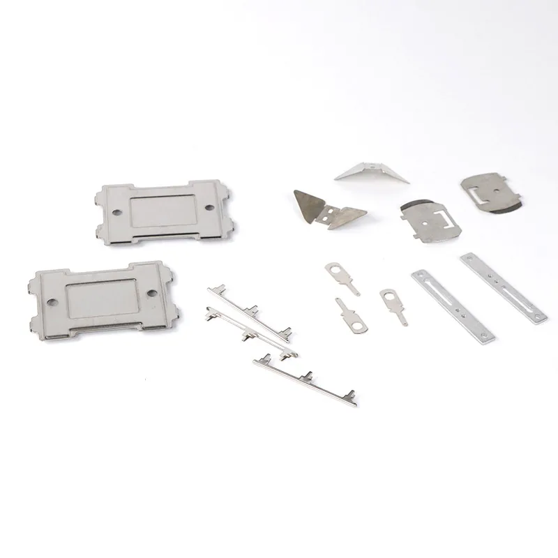
Metal Stamping Holes, Slots and Bends: A Buyer Design Guide
A practical guide for buyers and engineers preparing custom stamped parts. Learn which drawing details help a supplier review holes, slots, tabs and bends before tooling or sample work begins.
State the part’s job, mating component and installation direction.
Show feature locations from clear functional references.
Ask the supplier to review material, forming sequence and inspection plan.
Approve the drawing or sample before moving into the next stage.
Why Hole, Slot and Bend Relationships Matter
A stamped component is often described with simple language: two holes, one slot and a formed return. In use, however, those details work together. A mounting hole may need to line up with a mating screw after the part has been bent. A slot may exist to allow adjustment, route a cable, capture a tab or make room for an adjacent assembly feature. A bend may provide stiffness, clearance or a retaining action. The drawing needs to communicate that relationship.
That is why a buyer should treat metal stamping holes and bends as a design-review subject rather than just a list of dimensions. The question is not only whether a round opening can be pierced or whether a bend can be formed. It is whether the selected material, thickness, shape, feature position and inspection reference allow the finished part to do its intended job. The answer depends on the drawing and the application, so a reliable supplier review is more useful than a copied numerical rule.
For example, a hole that looks non-critical in a flat layout may become important after forming because it locates a cover, a spring, a fastener or a mating bracket. A narrow bridge of material between a slot and an outer edge may be acceptable for one design but need further consideration in another. A short formed flange may serve as a stop, but its practical result depends on material behavior, tooling and required appearance. These are normal design-for-manufacturing conversations, not defects in the request.
Good communication at this stage also prevents a common purchasing problem: comparing quotations that are based on different assumptions. If one supplier interprets a hole position from the part edge and another interprets it from a bend line, the parts may not be reviewed on the same basis. Clear references, a short note about assembly and a request for questions before production make the quotation process more meaningful.
Start with Function and Functional References
Before deciding how to dimension a hole or a bend, write one sentence about what the part must do. Examples include: hold a small enclosure to a frame; guide a wire route; retain a cover; provide a mounting point; create a spring contact; or support an internal component. This sentence gives context to the drawing review and helps a supplier identify the features that deserve closer attention.
Next, identify the references that matter to assembly. A functional reference can be a locating edge, a centerline, a mating face, a center bore, a tab interface or a finished bend surface. Use these references consistently. If the critical hole must align with a mating boss after forming, show its relationship to the same reference used by the mating part. If a slot is intended to provide adjustment, label the direction of adjustment and the usable travel rather than leaving the purpose open to interpretation.
Useful drawing notes
Identify material when known, thickness range when available, finished orientation, cosmetic faces, mating components and any dimensions that control fit.
Useful purchasing questions
Ask whether a feature needs a drawing clarification, whether a sample is recommended, and what measurement reference will be used for the critical interfaces.
There is no need to invent a tolerance or manufacturing method just to make a drawing appear complete. If a dimension is critical but the allowable variation has not been established, say that it is subject to assembly confirmation. If the material grade is open, describe the operating environment and ask for options. This approach is clearer than presenting unsupported requirements as fixed facts.
Buyers who are new to custom forming can also review the broader process in our metal stamping design guide. The purpose of this article is narrower: to make holes, slots and bends easier to discuss during an RFQ and drawing review.
Designing Pierced Holes for Assembly
Round holes are used for screws, pins, rivets, drains, alignment, access and clearance. Their purpose should be reflected in the drawing. A clearance hole, for example, may be sized around a mating fastener and its assembly allowance. A locating hole may be tied to another locating feature. An access hole may be shaped around a tool or connector. These uses create different questions for the engineering review even when the openings look similar.
Show the hole diameter, quantity, pattern and reference dimensions. Where possible, show whether a hole is through, formed, countersunk, threaded after stamping, or intended for a later operation. If the finished part has an inside and outside face, identify which face is important. The punch side, burr direction and cosmetic expectation can matter for some assemblies, especially for clips, contacts, covers and visible hardware.
A supplier may also ask about the distance from a hole to an edge, another opening or a bend. That is not a request for unnecessary detail; it is a way to assess material flow, tool access and feature stability for the actual part. The appropriate spacing is project-specific. It varies with thickness, material condition, geometry and the process sequence, so it should be reviewed from the released drawing instead of assumed from a generic online chart.
| Hole purpose | Information that helps the review | Assembly question to answer |
|---|---|---|
| Fastener clearance | Mating hardware, hole reference, part stack and access direction. | Must the fastener pass freely after forming? |
| Location or alignment | Datum reference, mating pin/boss and critical relative dimensions. | What feature controls the final position? |
| Access opening | Tool, connector or actuator envelope; finished orientation. | What must pass through the opening? |
| Secondary operation | Thread, counterbore, insert or finishing requirement. | Does the feature need a later process? |
When a part needs closely coordinated holes and formed features, a first article inspection discussion can be useful. It gives the buyer and supplier a chance to agree on the drawing, sampling and measurement priorities before the next stage is considered.
Slots, Tabs and Narrow Webs
Slots are not simply elongated holes. They may provide adjustment, engage a tab, reduce weight, create a controlled break line, offer connector clearance or establish a flexible section. A slot should therefore include its length, width, end shape, orientation and functional reference. If only part of the slot is usable for adjustment, identify the usable area in the drawing or assembly note.
Tabs are equally functional. A tab can lock a component, guide assembly, receive a folded feature or create a contact point. When a tab is bent, the final angle, direction and engagement face are often more important than the flat outline by itself. A simple side view, an isometric view or an assembly sketch can remove ambiguity.
Pay attention to the material left between a slot, hole, edge or bend. This remaining area is often called a web or bridge. A very narrow area can change how a part behaves during forming and handling. Rather than declaring a universal minimum, mark the feature as important, show the functional reason and invite the supplier to propose a manufacturable arrangement. The response may include a drawing question, a tooling comment, a sequence suggestion or a sample recommendation.
For components such as clips, mounting straps and electrical contacts, the relationship between slots, tabs and formed sections is often central to function. See the Custom Hardware Parts category for examples of drawing-based industrial hardware work, then use your own drawing and assembly requirements for a product-specific review.
Holes Near Bends: Review the Finished Part, Not Only the Flat Pattern
A hole close to a bend deserves special attention because the finished position is what matters to the buyer. The flat position, bend line, material thickness, bend direction, tooling route and required part shape all influence how the feature is reviewed. A drawing that only shows the flat layout can leave questions when the actual use is in the formed condition.
Show a formed view or side view whenever a hole, slot, tab or edge works near a bend. Dimension the feature from the reference that matters in the assembled condition. If the critical requirement is a screw passing through a cover after the cover is folded, explain that. If a hole needs to remain clear of a mating flange, show the flange. If a punched opening is for a cable or connector after forming, include the envelope that must pass through.
The supplier may choose to pierce a feature before forming, after forming, or recommend an alternative based on the design. That decision should follow a drawing review. The buyer does not need to prescribe the tool sequence unless there is a specific validated reason to do so. What matters is that the part function, reference, material and acceptance condition are clearly stated.
This is also a useful place to separate design intent from a visual preference. If the outside face must remain smooth around a hole, write that requirement. If a small edge condition is acceptable because the feature is internal, say so. If the direction of a formed lip matters, include it. These notes allow a supplier to assess the finished component rather than treating every detail as equally critical.
Bend Geometry, Reliefs and Short Flanges
Bends are usually added to create stiffness, clearance, enclosure walls, mounting feet, spring action or a retention feature. A bend definition should show the angle, direction, inside or outside reference where relevant, and the finished dimensions that control installation. The drawing should also make clear whether an angle is nominal, whether it mates against another component, and whether the appearance of the bend area is important.
A short flange can be easy to describe but hard to evaluate without context. It may be a mounting foot, a stop, a hook or a return. Give the flange height, bend direction, relationship to holes and any mating detail. If the flange needs to sit flush against another surface, identify that surface. If it only provides general clearance, a less restrictive statement may be appropriate.
Reliefs are small openings or shaped areas that can be placed near bend intersections or corners. Their purpose is to manage material and avoid unwanted interaction between formed areas. Relief shape and placement should be reviewed in relation to the part rather than copied from an unrelated design. A compact bracket with several neighboring bends may need different consideration from a broad cover with a single return.
Show the bend direction
Use a formed view or a clear note. Two parts with the same flat pattern can have different function if their bends are in opposite directions.
Identify the critical face
Say whether the outside face, inside face, mounting face or cosmetic face controls the requirement around the bend.
Material and finishing choices can affect the visual and assembly expectations around formed areas. When an appearance or corrosion-protection requirement is part of the request, include it in the drawing package and review our guide to surface finishes for metal stamped parts for purchasing questions to consider.
Tolerances, Datums and Inspection Strategy
Not every dimension should be treated as equally critical. A workable drawing identifies the dimensions that control assembly, sealing, alignment, clearance or appearance. It also identifies the references from which those dimensions are measured. This is the role of datums and a sensible tolerance strategy: they connect the drawing to the part’s intended function.
For a formed bracket, a mounting hole pattern may be more important than the overall free edge. For a clip, the gap and engagement point may matter more than an unused outer contour. For a cover, a connector opening and mating face may carry the key requirements. Discuss these priorities with the supplier instead of applying a tight requirement to every feature without a functional reason.
Where a tolerance has not been established, do not invent one. State that the dimension is subject to drawing review, assembly review or sample confirmation. If an interface is critical, provide the mating component or its drawing when possible. This lets the supplier evaluate the requirement based on real information, not on an assumed standard.
Inspection should follow the same logic. An RFQ can ask how the supplier proposes to verify critical holes, slot width, formed angle, overall position or visual requirements. The answer may depend on the production route and the component. For a deeper purchasing checklist, read metal stamping tolerances for custom parts and then identify the tolerances that genuinely affect your assembly.
Burr Direction, Edge Condition and Secondary Work
Perforating and cutting operations can leave an edge condition that matters more in some applications than others. A wire path, hand-contact surface, sealing interface, electrical contact or visible hardware component may need an explicit edge expectation. Other internal features may not need the same level of attention. The drawing should make the distinction.
Use plain language: deburr if required; identify the preferred face; mark cosmetic surfaces; explain whether an edge contacts another part; and note any later coating, plating, polishing or assembly process. Avoid promising a particular result without agreement on the material, finish and acceptance standard. The correct requirement is the one connected to your application.
Secondary work may include tapping, welding, insertion, finishing, engraving, assembly or packing. A feature that is simple in the stamped blank can become more consequential after a secondary operation. For example, a hole may locate an insert; a tab may be welded; a slot may receive another formed component. Include these steps in the RFQ so the supplier can review the whole part path.
RFQ Checklist for Custom Stamped Features
A clear RFQ does not need to be long, but it should remove the assumptions that change the review. Start with the drawing revision and part quantity range. Add the material preference or operating environment, the intended assembly, and the features that are critical to fit or appearance. If you have a physical sample, photos showing the installed orientation can help; if you have a mating part, its dimensions or drawing may be more useful than a generic description.
| Send with the RFQ | Why it helps |
|---|---|
| 2D drawing and, where available, a 3D model | Clarifies flat geometry, formed views and references. |
| Material / thickness preference or operating environment | Supports a relevant material and process discussion. |
| Annual or batch quantity range | Gives context for the appropriate manufacturing review. |
| Mating-part or assembly information | Shows which holes, slots and bends control fit. |
| Critical dimensions and visual faces | Directs attention to the acceptance priorities. |
| Finish, packing and destination requirements | Allows a more complete supply discussion. |
Before sending, compare the request with our metal stamping RFQ checklist. It is designed to help buyers organize a practical inquiry without adding unsupported information. For a project discussion, use the contact form and include the drawing, material preference, quantity, application, critical interfaces and required finish.
Frequently Asked Questions
Should holes and slots be dimensioned from part edges or from datums?
Dimension them from the reference that controls their function. An edge may be suitable when the edge is the assembly reference; otherwise, a centerline, mating face or defined datum may communicate the requirement more clearly. Show the relationship in the formed condition when it affects assembly.
Can a hole be placed close to a bend?
It can be reviewed, but the appropriate arrangement depends on material, thickness, part shape, bend direction, required feature position and process route. Provide a formed view and ask the supplier to evaluate the drawing rather than relying on a generic spacing number.
What should I include for a slot used for adjustment?
Show the slot length, width, end form, direction of movement, the usable adjustment range and the feature or mating part that establishes the final position.
Do I need to specify burr direction?
Specify it when edge direction affects assembly, appearance, safety, sealing, wire routing or another functional requirement. If it does not affect the application, explain the relevant acceptance expectation rather than adding an unnecessary restriction.
Can a supplier review a drawing before quotation?
Yes. A useful RFQ asks for a review of material, features, critical dimensions, production assumptions and any points needing clarification. A final approach should be confirmed against the actual project information.
What is the best way to confirm a custom formed part?
Use an agreed drawing revision, identify the functional and visual requirements, and discuss a sample or first-article approach when appropriate for the project. The needed confirmation method depends on the component and its use.
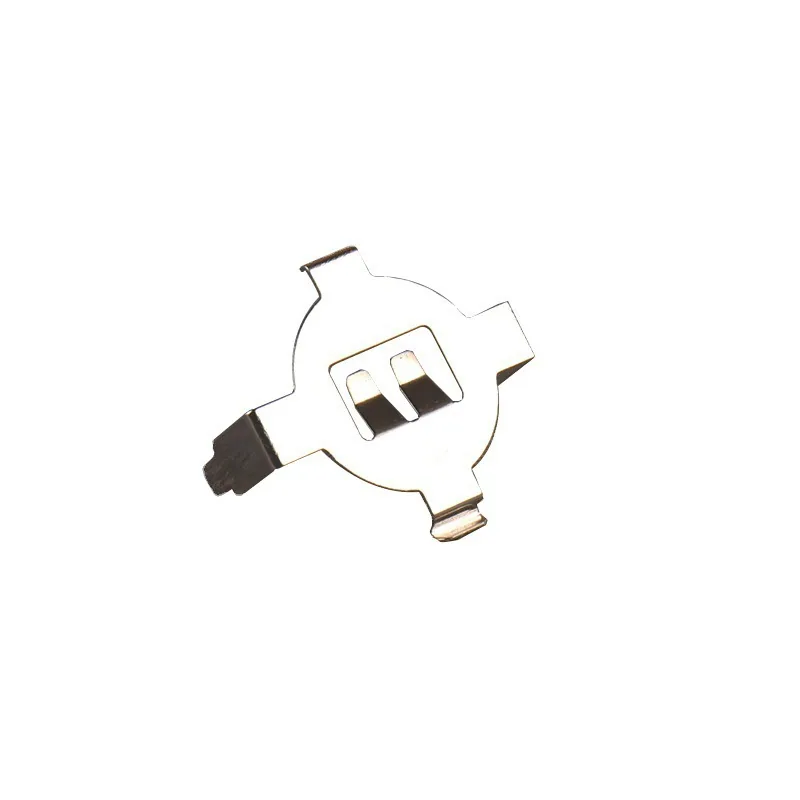
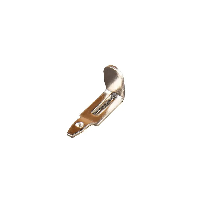
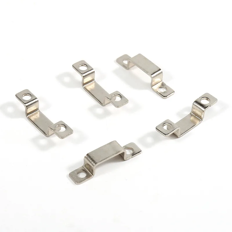
Turn the Drawing into a Clear Sourcing Request
The best outcome from a design guide is not a universal rule. It is a better conversation. When a buyer explains the function of a hole, slot or bend and supplies the references that matter after forming, a supplier can review the part with fewer assumptions. That leads to clearer questions, more comparable quotations and a more practical path toward sample or production confirmation.
If you are sourcing a drawing-based bracket, clip, strap, enclosure feature or custom hardware part, send the drawing revision, material preference, quantity range, application and the dimensions that control assembly. We can review the request and identify the details that need confirmation before the next step.